|
 |
|
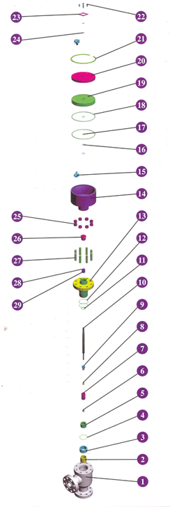
 ¡¡¡¡The hydraulic choke valve is used to be matchedwith manifold and other assemblies, which is appli-cable for flow-rate adjustment, that is, to raise or re-duce the valve core location is help for alternation offlow-way cross-area and flow-rate control. ¡¡¡¡The hydraulic choke valve is used to be matchedwith manifold and other assemblies, which is appli-cable for flow-rate adjustment, that is, to raise or re-duce the valve core location is help for alternation offlow-way cross-area and flow-rate control.
¡¡¡¡
Main technological parameters
Rated pressure£º2000-15000psi
Working temperature£ºPU
Working medium£ºetroleum¡¢natural gas
¡¡¡¡
Parts List£º
Item |
Component |
Qty |
Material |
Remark |
1 |
Body |
1 |
30CrMo |
|
2 |
Bushing |
1 |
FKM |
|
3 |
Seat Bushing |
1 |
30 CrMo |
|
4 |
O-Ring |
1 |
NBR |
|
5 |
Seat |
1 |
YG8 |
|
6 |
Stop Nut |
1 |
45 |
|
7 |
Valve Core |
1 |
YG8 |
|
8 |
Lower Diversion Bushing |
1 |
2Cr13 |
|
9 |
Upper Diversion Bushing |
1 |
2Cr13 |
|
10 |
Stem |
1 |
2Cr13 |
|
11 |
O-Ring |
1 |
NBR |
|
12 |
O-Ring |
2 |
NBR |
|
13 |
Bonnet |
1 |
30CrMo |
|
14 |
Cylinder |
1 |
30CrMo |
|
15 |
Cylinder Adapter |
2 |
30CrMo |
|
16 |
O-Ring |
2 |
NBR |
|
17 |
O-Ring |
2 |
NBR |
|
18 |
O-Ring |
2 |
NBR |
|
19 |
Piston |
1 |
45 |
|
20 |
Cylinder Cover |
1 |
30CrMo |
|
21 |
Circlip |
1 |
65 Mn |
|
22 |
Screw |
4 |
30CrMo |
|
23 |
Washer |
1 |
30CrMo |
|
24 |
O-Ring |
2 |
NBR |
|
25 |
Bonnet Nut |
8 |
40 Cr |
|
26 |
Packing Gland |
1 |
40 Cr |
|
27 |
Bonnet Stud |
8 |
30CrMo |
|
28 |
Packing Ring |
2 |
2Cr13 |
|
29 |
Stem Lip Packing |
5 |
FKM |
|
|
|
|
| |
|
| |
|
|
|

